
Start by preserving the first failure
A test mismatch can put engineering, quality and purchasing under pressure at the same time. Reworking a board immediately may change the evidence; repeatedly loading it until it passes can hide a problem that still needs an explanation. Begin with a controlled hold and a short investigation record.
Record the board identity, failed step, measured value and unit, acceptance limit, timestamp, test program version, fixture identity and relevant setup conditions. Keep the sequence of every subsequent attempt. These are recommended investigation controls, not a claim that VeriPCB has diagnosed a particular customer failure.
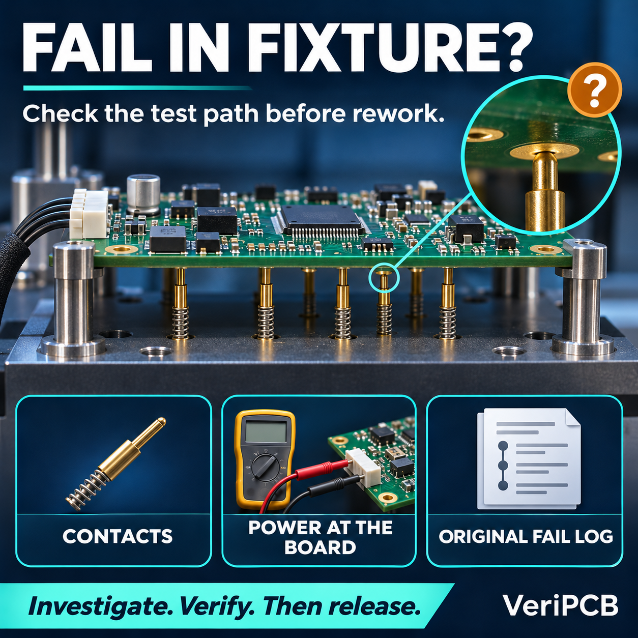
Could the result come from the test path?
Fixture connections are a credible hypothesis. NI’s Electronics Manufacturing Test brochure, Fixturing section, identifies fixture connectivity as a source of false failures. That principle supports checking the interface; it does not show that a particular failed board is good.
Inspect seating, alignment, support, probe travel and the accessible connection path using the fixture and probe maker’s instructions. Check relevant maintenance history and whether the symptom changes after an approved intervention. Do not use a universal cleaning method or apply extra clamp force without checking the equipment instructions. A product defect can also respond to pressure, temperature or movement.
Check voltage where the board receives power
The power-supply setting and board input voltage can differ. Rohde & Schwarz explains the effect of supply-lead resistance in Understanding Remote Sense. Measure at the relevant board input under the test load and compare against the product requirement. A steady reading may not reveal a short startup disturbance; choose the measurement method for the symptom.
Remote sensing may be appropriate on supported equipment, subject to the instrument manual, connection arrangement and protection limits. It is not a universal retrofit. Do not increase supply voltage simply to obtain a passing result. The test plan should define the operating condition being evaluated.
A practical comparison for the investigation
The proposed controls below are a buyer checklist, not measured before-and-after results or a statement of included VeriPCB services. Numerical requirements must come from the product specification and agreed test plan.
| Decision dimension | Common gap or risk | Proposed control and evidence |
|---|---|---|
| Original failure | A later pass overwrites the first result. | Retain first attempt, values, limits and all retest events against the same board ID. |
| Test configuration | Bench and fixture use undocumented differences. | Record test-program, firmware and fixture revisions plus relevant operating conditions. |
| Contacts and seating | A reseat is treated as proof of a fixture fault. | Inspect the interface and document observations before and after an approved intervention. |
| Input power | Only the supply-terminal setting is checked. | Measure the relevant board input under load; define measurement method and required range. |
| Reference boards | One repeatedly passing board is treated as universal proof. | Identify reference units and their expected behavior; check which functions and limits they actually challenge. |
| Repeatability | Attempts continue until a pass appears. | Agree a bounded repeat-test plan, unchanged limits and a rule for escalation. |
| Station comparison | A different bench result is accepted without correlation. | Compare the same units under matched conditions and record remaining differences. |
| Yield reporting | Retest passes are mixed into first-pass yield. | Separate first-attempt results, retest outcomes and independently resolved causes. |
| Release decision | The most recent pass becomes the release rule. | Require an authorized disposition supported by investigation evidence and agreed acceptance criteria. |
Compare stations without losing the evidence
- Keep the original unit and failure record together; do not substitute a different board silently.
- Match supply conditions, load, firmware, test sequence, timing and environment wherever relevant.
- Use identified reference units with established expected behavior and periodic review.
- Check whether a reference unit can reveal the fault mode of interest; a good board alone cannot prove that a station rejects defective boards.
- Change one investigation variable at a time where practical and record the change.
- Preserve unchanged product limits unless a separate engineering change is justified, approved and recorded.
A cross-station comparison can reveal where to investigate next. It does not by itself establish measurement accuracy or validate the complete test system. If results lie close to a limit, ask the responsible test engineer to review measurement uncertainty, resolution and decision rules. Define the investigation sample size and retest count for the risk; this guide sets no universal number.
How to interpret a pass after retest
Use a provisional category such as “inconsistent result, investigation open” until evidence supports a cause and disposition. A false rejection means the test incorrectly rejected a conforming unit; do not assign that category simply because a later attempt passed. An intermittent board fault, setup difference or inadequate test method may still be present.
When a controlled correction is made, record what changed and repeat the agreed checks. Keep any rework, replacement and retest history traceable. Report first-pass yield separately from final disposition so that repeated attempts do not make the initial test process appear more stable than it was.
Where this checklist applies
This guide concerns inconsistent results in populated-board production testing. It is useful for industrial sensing and process-control OEM teams planning NPI, supplier qualification or an existing-line investigation. It does not replace product-specific safety, regulatory, calibration or acceptance requirements. Test access, fixtures, reference units, measurement methods and investigation responsibilities should be agreed before the build.
Questions about PCBA fixture failures and retests
Does passing on a bench prove the production fixture is wrong?
No. The bench may use different power, loads, timing, firmware or coverage. Compare the conditions and preserve the first failure before assigning a cause.
Can we accept a PCBA after it passes on a second attempt?
Follow the approved product-specific retest and disposition rules. A later pass does not erase the earlier failure or prove the absence of an intermittent defect.
Should we widen test limits to reduce false rejects?
Do not change limits solely to improve the pass rate. Investigate the measurement and product behavior; any limit change needs a justified, approved engineering change and appropriate verification.
Start with the symptom, without sharing design files
If this is holding up a build, begin with the failing step, application, approximate quantity and whether the result changes after reseating or moving stations. Contact andy@reach.veripcb.com or use the project enquiry form. Agree a suitable private transfer method before sending confidential Gerber, BOM or test files. No design files are required to start a discussion.
Working through an inconsistent test result?
You are welcome to start with a non-confidential description of the failing step, application and build stage. Test development, fixture work, investigation scope and acceptance requirements need project-specific agreement. We provide both PCB manufacturing and PCBA assembly services.
Discuss my test requirements